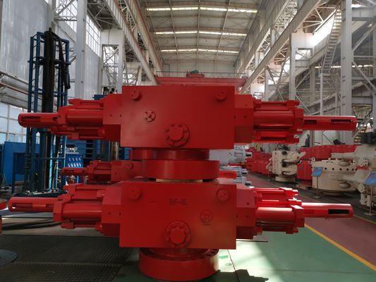
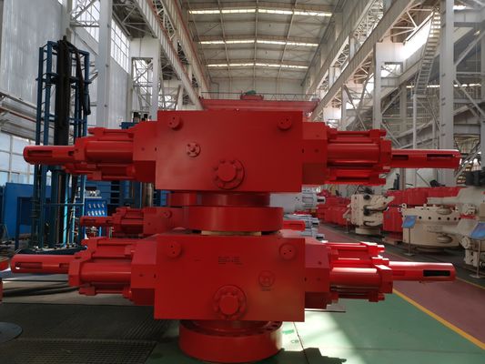
Hydraulic Open And Close Bonnets Blowout Preventer Control System Bottom Flanged
Introduction of Blowout Preventer Control System
Hydraulically or manually operated locking mechanism.
Includes secondary seal.
Offers flat and side door structures or hydraulic control type flat door structures.
The side door and shell are connected through triple hinges.
To open and close the valve in sequence, use the pressure bar (C type ram BOP).
The guide frame is positioned at the end of the side door. Upon opening the door, the ram can be pulled along the guide rail and replaced, specifically the D type ram BOP Pistons indicator. Upon opening the door, the ram can be pulled along the guide rail and replaced, specifically the D type ram BOP Pistons indicator.
Upon opening the door, the ram can be pulled along the guide rail and replaced, specifically the D type ram BOP Pistons indicator.
An oilway is intentionally concealed.
The ram cavity's shape is elliptical.
Technical Specification of Blowout Preventer Control System
Item |
Single ram bop (with booster) |
Double ram BOP (one chamber with booster) |
||
Model | 13 5/8”-5000psi | 13 5/8”-5000psi | ||
Upper connecting type | Studded | Flanged | Studded | Flanged |
Lower connecting type | Flanged | Flanged | Flanged | Flanged |
Weight Kg | 5680 | 5888 | 10371 | 10651 |
Height H mm | 750 | 960 | 1285 | 1495 |
Gravity G mm | 490 | 515 | 805 | 830 |
Performance requirement level | PR2 | |||
Bore | 346.1 mm (13 5/8″) | |||
Test pressure of hydro-static pressure | 51.8MPa (7,500psi) | |||
Rated working pressure | 34.5MPa (5,000psi) | |||
Hydraulic control system strength pressure | 31.1MPa(4,500psi) | |||
Hydraulic control system rated working pressure | 20.7MPa(3,000psi) | |||
Recommended hydraulic control system operation pressure | 8.4~10 .5MPa(1,222~1,518psi) | |||
Cylinder diameter | 342.9mm(13 1/2″) | |||
Booster diameter | 250mm(9 7/8″) | |||
Oil volume required by opening one pair of ram | 41L | |||
Oil volume required by closing one pair of ram | 43L | |||
Oil volume required by closing one pair of ram(booster) | 63L | |||
Interface thread of hydraulic control pipe line | NPT 1 | |||
Specification of side outlet | 3 1/8″-5,000psi | |||
Temperature Rating | T-20/250(-29~121℃)(Or subjects to the contract) | |||
Temperature Grades of Metal Material | T20/250(-29~121℃)( Or subjects to the contract) | |||
Temperature Grades of Metal Material | BAB(extreme low pressure -18℃, continuous high temperature 66℃, extreme high temperature 93℃) (Or Subjects to the contract) | |||
Closing Ratio | 10.83:1 | |||
Closing Ratio(with booster) | 17.4:1 | |||
Ram size for fitting |
CSO, 2 3/8″, 2 7/8″, 3 1/2″, 4 1/2″, 5″, 5 1/2″, 7″, 9 5/8″, 9 7/8″, 4″,10 3/4″, 7 5/8″, 6 5/8″, 7 1/2″, 2 7/8″~5″, 3 1/2″~5 1/2″, 41/2″~7″, 2 3/8″~3 1/2″, 3 1/2″~5 7/8″, 3 1/2″dual hole, 2 7/8″dual hole, 2 7/8″X3 1/2″dual hole, ordinary shear ram, Sulfur-resistant Shear Ram Note:It can install same type Cameron Ram (except shear ram) |
|||
Note: The design and manufacturing of BOP are subject to API Spec 16A specification. The parts contacting with well fluid within BOP shall be able to resist hydrogen sulfide stress corrosion and all metallic parts contacting with well fluid meet the requirements of NACE MR-01-75/ISO15156.(except shear ram)
|